Assemble the Raspberry Pi Cat Laser Pointer Toy
Apr 26, 2018
In part one we discussed what exactly we're trying to build, and what's needed to begin assembling our cat laser pointer toy. Here in part two we're going to take all the pieces we've gathered and assemble them into one beautiful creation.
The goal of this part?
- Assemble the pan/tilt mount and servo motors.
- Solder the laser diode to the NPN transistor, and attach it to the shark(!!!).
- Solder the physical push button.
- Connect all the pieces together
If words like solder and transistor are a bit intimidating, don't let them be! It's really not that difficult, promise.
Later on in part three we'll cover how to write code to fire the laser in a pseudo-random fashion at the touch of a button. As a bonus, part four will take this one more over-engineered step and demonstrate how to trigger the laser remotely as well as on a schedule, should you be so inclined.
Assemble the Pan Tilt Mount and Servo Motors
The pan/tilt mount provides a convenient way for us to use our servo motors as a means to navigate the cartesian plane. We will be using one of the servos as the x-axis, and the other as the y-axis.
Our servo motors can rotate from 0 to 180 degrees, no more no less. In order to provide a full range of motion for our laser contraption after we assemble all the pieces, we should first ensure the starting point of each servo is where we want it.
The servo traveling along the x axis will be responsible for moving the laser left and right. In order to accomplish this we should have a center position once mounted of 90 degrees, which allows it to turn left to 0 degrees, and right to 180 degrees.
The servo traveling along the y axis will handle moving the laser up and down. For this, we'll want the starting position to be 0 degrees, which will aim the laser straight out once mounted, while 90 degrees will aim straight down and 180 degrees will, well, aim the laser backwards. We won't have much use for anything over 90 degrees on the y axis, but it's good to note.
Calibrating the X and Y Servos
The first step to calibrating our servos is to designate one as the x axis and the other as the y axis. I wrapped a piece of electrical tape around the x axis wires for quick identification, which helped avoid confusing the two later on.
Now that we've identified the servos, it's time to write some code to set them in the correct starting positions before we actually attach them to the pan/tilt mount. If you're using the same servos as me, they have power, ground and control wires.
Connect three of your male-to-female jumper cables to your servo pins. Now, using the GPIO diagram below as reference, connect the female connectors to the Pi’s GPIO headers as follows:
| X Servo | Y Servo |
|
|
The servos are now connected and ready to be calibrated. Nice work!
Writing Code to Calibrate the Servos
Before getting started, let’s update our Pi to the latest packages and install the GPIO library. Run the below commands in the terminal:
Note: if this is the first time you're running these commands it may take a bit to complete, so hang tight.
sudo apt-get update sudo apt-get upgrade sudo apt-get install rpi.gpio
We’re all set, it's time to create the calibration script. Create a new file called Calibrate.py with the following code in it:
#!/usr/bin/env python

import RPi.GPIO as GPIO
import time

GPIO_X_SERVO = 4
GPIO_Y_SERVO = 17

if __name__ == '__main__':
    GPIO.setmode(GPIO.BCM)

    GPIO.setup(GPIO_X_SERVO, GPIO.OUT)
    GPIO.setup(GPIO_Y_SERVO, GPIO.OUT)

    print "calibrating..."
    try:
        x_servo = GPIO.PWM(GPIO_X_SERVO, 50)
        y_servo = GPIO.PWM(GPIO_Y_SERVO, 50)

        x_servo.start(7.5)  # X Servo: 7.5 is 90 degrees
        y_servo.start(2.5)  # Y Servo: 2.5 is 0 degrees

        time.sleep(1) # give the servos a chance to move

    finally:
        GPIO.cleanup()
The above script is is pretty minimal: each time it runs the x servo will be set to its center at 90 degrees, while the y servo gets set to its starting point of 0 degrees.
You need only run this once.
In the terminal, navigate to the directory that has this newly created python script in it. Once there, type chmod +x Calibrate.py and press enter to make the script an executable, then type ./Calibrate.py. If there were no issues in your script, you should have heard the motors spin to the desired positions.
Excellent! We now have two servos pointing in the correct starting positions. You can unplug the servo wires from the GPIO pins, it's time to attach them to the pan/tilt mount.
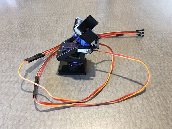
Attach the Servos to the Pan Tilt Mount
Attaching the servos to the pan/tilt mount went fairly smooth with the exception of one rather important part: the two white plastic servo attachments, despite coming with the pan/tilt mount, didn't fit perfectly in their designated spots. You may not have this issue, but I ended up using scissors and a box cutter to pare them back a bit where necessary, which is apparent in the below image: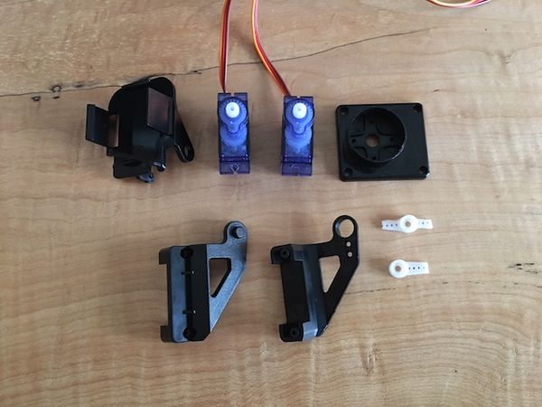
When piecing this together it's important to keep in mind that the servos are calibrated right now to their starting positions, but we haven't attached the white plastic arms yet. When it comes time to attach them, the servo should be positioned in a way that when the plastic arm is attached, it's aligned as follows, without the need to manually rotate the motor: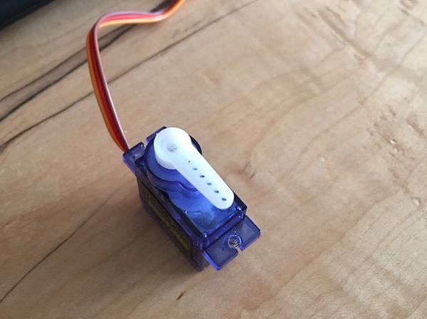
I demonstrate this a bit further a couple images down. As for the assembly itself, just in case you're having trouble piecing it together here's a few screenshots of the progress as I went.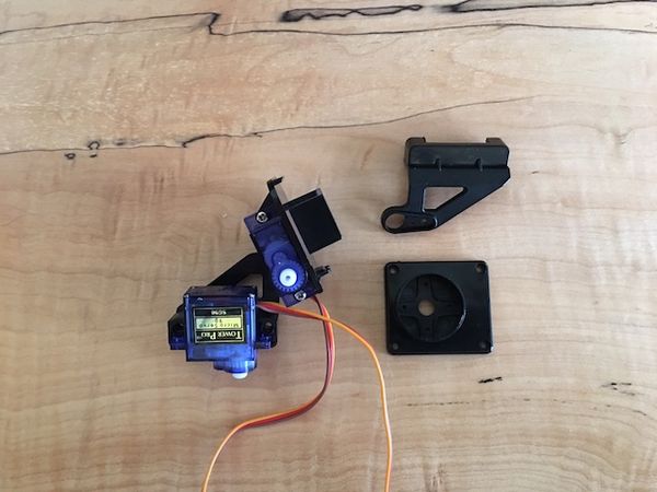
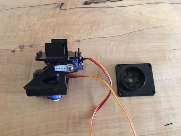
The previous image showcases a couple of important points:
- I consider the
frontof this pan/tilt mount to be the side where the wires leave the servo motors. This allows sufficient movement when the mount is on a flat surface. Alternatively, thebackin this case (opposite side) could be used when your intention is to have the mount on its side (e.g. on a wall, or fridge). - The top of the mount where the
y axis servois attached was positioned as flat as can be before screwing in the servo arm. If you recall, we want they axisto have a starting position of0 degrees. If you can imagine a laser sitting on top of the mount in this position, aiming the direction of where the wires are coming out, it would be shooting straight. Tilting the mount to90 degreeswould cause the laser to aim straight down, and so on.
I decided to use similarly colored jumper cables as the built-in servo wires to help reduce the amount of confusion while connecting them later. Red is power, brown is ground and orange is control.
Now that we have motors calibrated and attached to the mount, it's time to setup the laser.
Prepare the Laser Diode
The laser diode has two wires: power and ground. It does not have a third wire for control. The GPIO pins on your Raspberry Pi output 3.3v when turned on but don't provide enough current to make the laser glow to a brightness worth chasing. The 3V3 regulated pin (e.g. pin 1 on the Pi) provides the necessary current, but cannot be logically toggled on and off by our code. On one hand we have control but insufficient current, and on the other hand we have sufficient current without control. How do we get around this?
Enter the NPN transistor. We'll leverage this little device as a way to introduce control into the equation. The NPN transistor has three connections: the base, which is what our control wire will connect to, the collector and the emitter. The transistor is used as an electronic switch, which logically connects the collector with the emitter once electricity hits the base.
With that said, we're going to attach the laser diode to the shark (please tell me you bought the shark!), then we'll solder the laser and some additional wiring to the NPN transistor.
Using a hot glue gun (or some other form of adhesive), attach the laser diode to the sharks head, like so: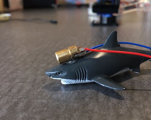
Once the glue dries, take three (3) wires that have at least one female connector and snip off the opposite end of the female connector. Then, strip about an inch of this newly snipped end from its casing to expose the wiring inside. You should be left with three wires having one female end and one stripped end. These three wires will be used to connect the laser/ transistor to the Raspberry Pi's GPIO pins.
Take one more wire, snip off both ends and strip about an inch of casing from either side. This wire will be used as an extension between the laser diode and the transistor to provide some needed slack.
The screenshot below demonstrates the three female wires and one extension wire soldered to the transistor as follows:
- The green wire is soldered to the transistor's
emitter, and will eventually connect to the Pi'sgroundGPIO. - The purple wire is soldered directly to the laser diode's power wire, and will provide power to the laser.
- The blue wire (not the one connected to the laser diode) is connected to the transistors
base(middle connection), and will be used as ourcontrol. - The laser diode's ground wire is connected to an extension wire (yellow below), which is then connected to the transistor. Again, this is to provide additional slack so the wire can reach the GPIO pins once mounted.
I wrapped the soldered parts with electrical tape to give them a bit of protection.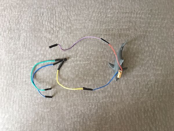
Now that everything is soldered together, let's give it a test drive! Using the above image, wire coloring and previously shown GPIO diagram as reference, connect the laser to the Raspberry Pi as follows:
- Purple connects
pin 1 (3V3 Power) - Blue connects to
pin 13 (GPIO27) - Green connects to
pin 25 (Ground)
With the connections in place, create a new file called LaserTestDrive.py and paste the following code snippet inside:
#!/usr/bin/env python

import RPi.GPIO as GPIO
import time

GPIO_LASER = 27

if __name__ == '__main__':
    GPIO.setmode(GPIO.BCM)
    GPIO.setup(GPIO_LASER, GPIO.OUT)

    print 'blinking laser...'
    try:
        # Test turning the laser on and off
        time.sleep(1)
        GPIO.output(GPIO_LASER, 1)
        time.sleep(1)
        GPIO.output(GPIO_LASER, 0)
        time.sleep(1)
        GPIO.output(GPIO_LASER, 1)
        time.sleep(1)
        GPIO.output(GPIO_LASER, 0)

    finally:
        GPIO.output(GPIO_LASER, 0)
        GPIO.cleanup()
In the terminal, navigate to the folder that contains the above script and type chmod +x LaserTestDrive.py to make it an executable. Now, type ./LaserTestDrive.py to kick off the script. If done correctly, you should see the laser flash multiple times. Boom baby!
We now have a shark with a freakin' laser beam attached to it's head. Dr. Evil would be proud. It's time to set ourselves up with a physical push button so, later on, we can actually engage the cat laser pointer toy at the press of this button.
Setup a Physical Push Button
Take two (2) female-to-any wires from your stash, snip off the non-female end, then strip about an inch of casing to expose the wires. If you're using the same button as me, flip it over and you'll see two parallel plastic lines running the length of the button, inline with the metal connectors. Twist and solder your wires to the buttons metal connectors, one wire per plastic line. Here's how mine came out: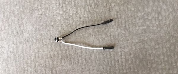
With the soldering in place, use the previously mentioned GPIO diagram as a reference and connect the wires as follows:
- Black connects to
pin 39 (Ground) - White connects to
pin 37 (GPIO26)
Now that everything's wired in, let's test our little button out. Create a new file called Button.py with the following code in it:
#!/usr/bin/env python

import RPi.GPIO as GPIO
import time

GPIO_BUTTON = 26

if __name__ == '__main__':
    GPIO.setmode(GPIO.BCM)
    GPIO.setup(GPIO_BUTTON, GPIO.IN, pull_up_down=GPIO.PUD_UP)

    print 'Press the button 3 times to exit...'

    press_count = 0
    while press_count < 3:
        # Test pressing of the button!
        button_pressed = GPIO.input(GPIO_BUTTON) == False
        if(button_pressed):
            print 'Button Pressed!'
            press_count += 1

            # pause to avoid the button press being picked up multiple times
            time.sleep(0.5)

    GPIO.cleanup()
In the terminal, navigate to the directory where this new script lives and type chmod +x Button.py to make it executable. Afterwards, run the script by typing ./Button.py. Once running, pressing the button should print Button Pressed! in the terminal. Press the button three total times to have the script exit.
Fantastic work! You've accomplished a lot so far. Now it's time to put all those disparate pieces together.
Connecting All the Pieces
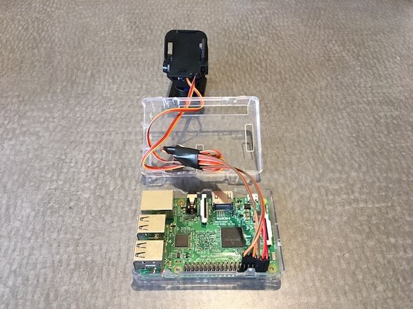
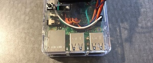
At this point we prepared all the individual pieces and ran some tests to ensure they're functioning as we expect. Now it's time to put it all together. If you're using the same Pi case as me, open it up and place the Pi inside, but leave the top piece detached. The top of the case has a rectangular opening which exposes the GPIO section of the Pi, we'll use this to fish some wires through. With the Pi in place, let's get to assembling:
We'll start off by wiring up the pan/tilt mount. Fish the servo wires through the rectangular opening in the top of the Pi case, then connect them to the GPIO's as follows:
| X Servo | Y Servo |
|
|
Next up is attaching the shark and laser to the pan/tilt mount. I used velcro which allowed for a less permanent solution should I decide I want to turn the shark around. As was mentioned before, the servos have a finite range of motion. Right now we're treating the front of our mount as the side where the wires exit the servos. Deciding to treat that as the back of our mount would allow for an entirely different range of motion.
I used a hacksaw to trim away some of the plastic on top of the pan/tilt mount prior to mounting the shark. This allowed for less interference and better positioning, but is not strictly necessary.
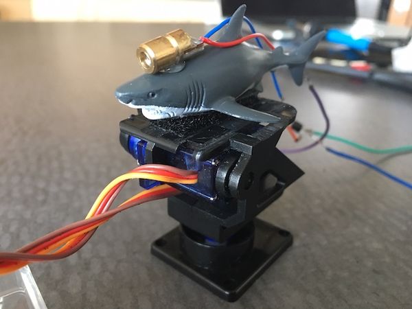
Once the shark is mounted, fish the wires and NPN transistor through that same rectangular opening in the Pi case, then connect them as follows:
- Purple connects
pin 1 (3V3 Power) - Blue connects to
pin 13 (GPIO27) - Green connects to
pin 25 (Ground)
The mount and shark laser are primed and ready, time for the push button. I fished these wires through a different hole on the case to avoid overcrowding the GPIO opening. Fish them through wherever works, then connect as follows:
- Black connects to
pin 39 (Ground) - White connects to
pin 37 (GPIO26)
I didn't use any adhesive or other trickery to keep the button in place. The wiring and positioning of the button actually made it naturally stationary, enough for my needs anyway.
Finally, it's time to attach the pan/tilt mount to the case itself. For this I went the overly complicated route of drilling out holes in the case to screw the base of the mount into. A much simpler and less permanent solution would be to use velcro. Velcro is plenty strong enough to support the weight of our little contraption.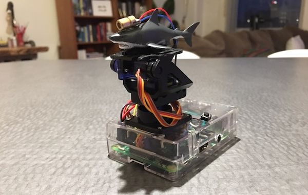
Congratulations, you now have a super evil cat laser pointer toy assembled and ready for action. Now we just need to give it life in the form of python code.
Conclusion and Next Steps
Part one set the goals and outline. Now with part two wrapped up we have a fully assembled cat toy laser. I'm heading to part three where we'll write the python code to make all these parts function together at the push of a button.
Later in Part Four I'll be covering how to trigger our cat laser pointer toy remotely as well as on a schedule. First, let's figure out how to trigger it by pushing that button we just installed.


Comments
Leave a Comment